Introduction
Back in 2003 I was doing some work in the company’s accounting department when all of the PC’s in the area flicked off and rebooted again. It was so fast and simultaneous that I thought that we’d had some kind of electrical fault that hit that part of the office, and I didn’t think too much about it. Comparing notes with one of the other IT guys much later on, he had also noticed the same thing in another part of the office.
Sometime later, our Internet connection was down. Or so I thought.
I got in touch with our ISP and they checked and told me that, no, the connection was up and there was actually a LOT of traffic going through it. So I went into the computer room to check.
Back in those days, our connection between the our firewall and the T3 modem was through an old 10Base-T hub. Not a switch, but a hub. This was okay, because these were the only two devices on the hub, and the 10Mbps, was still faster than our Internet connection.
The hub had a little red light on it that flashed whenever it detected a collision when two nodes try to transmit at exactly the same time and interfered with each other. During normal operations, you’d expect that light to flicker once or twice a minute. Any more, and you likely had a problem brewing.
Well, I went into the computer room and that collision light was solid.
Not flickering, just on.
There was so much traffic going down that hub that it was jammed up into constant collisions and nothing was getting through. Back in those days, we hosted our own web sites on premises, and this meant that we had essentially been kicked off the web.
Our firewall logs had gotten so big in that short time that it had run out of disk space and stopped logging. I had to flush the logs and restart it just to find out what that traffic was.
It turns out that we had been hit with a worm. Probably the “Welchia”, or the “Blaster” worm. One of the characteristics of it was that, after installing itself, it caused the system to reboot. After that, each infected computer would start scanning like crazy to find more Windows systems that it could infect.
It was those scanning probe packets that were jamming up our internet connection. That simultaneous reboot that I had seen was actually a handful of computers getting infected at nearly exactly the same time.
We lost of few days of our lives to investigating this, working around it, and cleaning and patching the workstations.
At some point in our investigations, we determined that the virus was spread from a laptop that one of our sales/marketing guys was using. He had taken it home or to a client site, and plugged it into a network and got infected. Then he came into the office and plugged it in - behind our firewall.
It was like the babysitter late at night in the horror movie. The phone call is coming from the basement - inside the house!
We had no defence against this.
Smart Home Devices
None of us have no problem going to the electronics store or the hardware store or the appliance store and coming back with some new “smart” device. A fridge. A robot vaccuum. Even a smart plug.
And when we get it home, we take it out of the box, connect to it from our phones and give it our wifi password.
Now it’s in our networks. Behind the firewall…inside the house!
Yeah. But what can a smart plug do?
Indeed. What if it opens a VPN tunnel back to some hacker den in North Korea? Really, I have no doubt that you could stuff enough brains inside a smart plug to do that. And once that’s done, the hackers half-way around the world can start poking around inside your entire home network. And you would probably never know.
I’m seeing articles on-line that some refrigerators with display screens on them are starting to show ads. What if you don’t want ads on your fridge? What if I don’t want my printer reporting back to HP about how many pages I print each month? And let’s not talk about “Smart” TVs.
I did a survey on my network, and between smart plugs and switches, robot vaccuums, garage door openers, streaming devices, smart speakers, printers and a few other things, I counted up about 45 devices.
What do I know about any of them?
Honestly, not much. So why trust them?
Zero Trust
When it comes to this stuff, “trust” is a very misguided concept.
Do you need to trust these things? The answer is, “No!”
What you need is a “Zero Trust” network design behind your firewall that lets you sequester these devices such that they can do no harm. Then you don’t care if they are malicious, because they’ve been neutralized.
Let’s look at how to do that…
TCP/IP Subnets and Routing
A quick note to start: This article is about IPv4 routing, not IPv6. So if you are using IPv6, then you won’t need the information here.
Before we can go any further, we’ll need to have a basic understanding about how devices find each other and communicate over TCP/IP.
If you’ve ever manually set up a device on a network without DHCP, you’ll know that you need to provide four pieces of information:
- The IP Address
-
This is the literally the address of the computer on the network. It’s going to be in the format of
###.###.###.###where each###is a number between 1-255 (ie. one byte). An IP address is always 4 bytes long. - The NetMask
-
This tells the device the address space of the subnet on which it sits. It will use this information to determine if a device that it wants to communicate with is on its own subnet or not. We’re going to use a netmask of
255.255.255.0or/24in CIDR notation for all the subnets in this article which means that the first 3 bytes of the address (or the first 24 bits of the address) represent the subnet while the last byte (8 bits) represents the device’s unique place in that subnet. - The Default Gateway
-
This should be considered to be a feature of the subnet, rather than the device that you are configuring (for purposes of this discussion). It tells the device the IP address of where to send its packets if it wants to communicate with a device that it has determined is NOT on its own subnet.
- The DNS Server Addresses
-
This is where to send requests for DNS lookups. It’s not relevant to this discussion.
How Devices Determine Routing
For purposes of this discussion, it’s probably best if you consider TCP/IP to be a “broadcast” protocol. This means, especially from the viewpoint of each individual device, that any packets it sends out are distributed throughout the subnet with an address attached to them. Only the device that has that address will pay any attention to it. In reality, modern switches and networking equipment handle the packet delivery without the need to actually send every packet to every device - but the devices don’t see that.
Each device knows its own IP address and its netmask so that it can determine if any other device with which it wants to communicate has an address on the same subnet as itself. If so, then it just broadcasts its packets on its subnet with the destination IP address on it. The other device will see its own address and get the packet.
If it determines that the other device is NOT on the same subnet, then it still broadcasts it on its own subnet, but this time addressed to the subnet’s default gateway - with the actual address of the destination somehow encapsulated inside it. The gateway will get the packet, and then relay it off in some manner so that it gets to its destination.
Here’s an example of what that would look like:
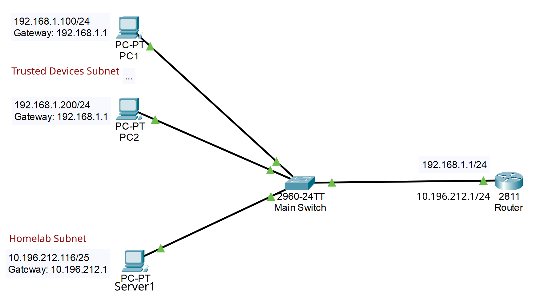
In this diagram, the top two PC’s belong to the 192.168.1.0 network, which is addresses 192.168.1.0 to 192.168.1.255. This is because they have the netmask 255.255.255.0 which you can see from the CIDR notation /24 in the addresses. These two computers can talk to each other directly.
If they want to talk to Server1, with address 10.196.212.116, then they will determine that it is NOT on their own subnet, so they have to send their packets to their default gateway, which is 2811 Router with the address 192.168.1.1. That router will then send it on to 10.196.212.116 through its second network interface, which has the address 10.196.212.1.
What’s very important to understand here is that all three PC’s are connected to the same switch! Even so, only PC1 and PC2 can talk to each other directly, and any other communication requires relaying through the Router.
This is because the physical topology of the network is irrelevant to the TCP/IP routing.
Routing With Firewalls
For this discussion, your really big takeaway should be this…
The router in the diagram with the name 2811 Router could be a firewall. As a firewall, it would have rules that control if and how devices communicate between subnets.
As a matter of fact, firewalls can only control traffic between subnets and not between nodes on the same subnet. For instance, in the diagram above, there is no way that the firewall at 2811 Router could control traffic between PC1 and PC2 because they can communicate directly without involving the router/firewall. On the other hand, rules in the firewall at 2811 Router will control communication between Server 1 and either of PC1 or PC2.
From this, you can deduce that the IP subnet is the basic building block of home network security.
Introducing VLAN’s
If you do some web searches about VLAN’s, you’ll find something like this introduction from Wikipedia:
A virtual local area network (VLAN) is a local area network broadcast domain that is partitioned and isolated in a virtual network at the data link layer (OSI layer 2). A VLAN behaves like a virtual network switch or network link that can share the same physical structure with other VLANs while staying logically separate from them.
VLANs work by applying tags to network frames that are forwarded within the broadcast domain, creating the appearance and functionality of network traffic that behaves as if it were split between separate networks. In this way, VLANs can keep network applications separate despite being connected to the same physical network, and without requiring multiple sets of cabling and networking devices to be deployed.
Essentially this is describing something that looks like this:
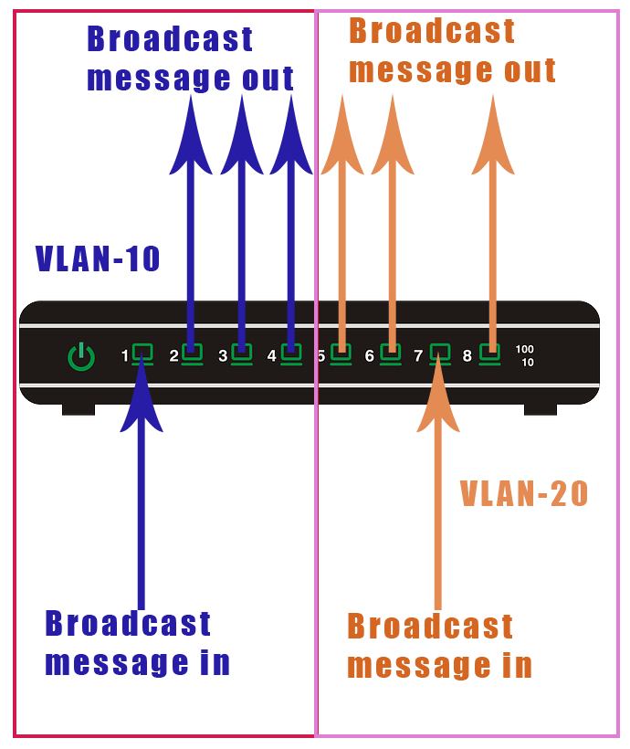
You can see that although all of the ports are on the same switch, ports 1-4 cannot communicate with ports 5-8. Essentially, this turns the single switch into two switches.
You can also split a VLAN across switches, like this:
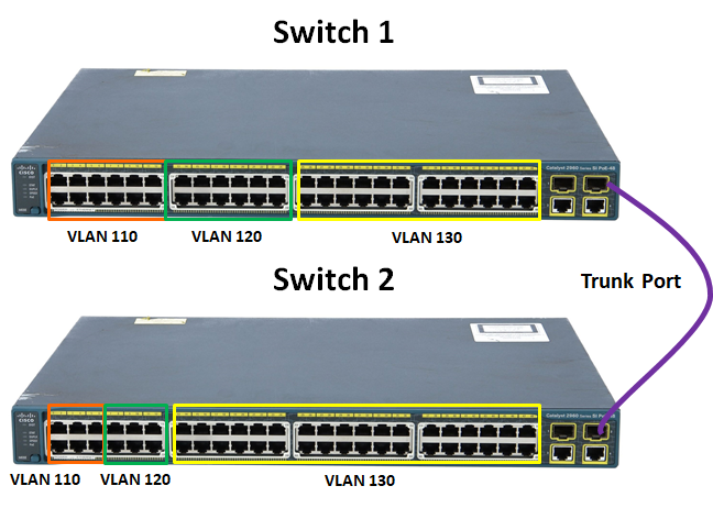
This divides both switches into 3 parts, and the ports in both switches can communicate with all of the ports of the same colour across both switches.
And that’s about all you’ll get before you’re really deep, deep into the weeds. You’ll quickly find out about trunks and IEEE 802.1Q and lots of other complicated stuff.
This seems like a cool idea…until you start wondering about how something on one VLAN can communicate with something on different VLAN.
After all, if you can’t do that, then your VLAN is 100% sequestered and inaccessible to and from the rest of the world. And that is quite a bit less than useful.
Managed Switches
Before we get into the details, we need to talk about one more thing…
Your standard, consumer grade network switch that you can buy for about $10 on any street corner probably won’t be able to handle VLAN’s. You’ll need something called a “Managed Switch”, which is generally marketted at corporate customers. They’re a bit more expensive than unmanaged switches, but you should be able to pick them up for $30 or less. You will, however, have to ditch any unmanaged switches that you already have - you could find a way to use them, but it’s not worth the hassle.
A managed switch will generally allow you to do a whole bunch of things in addition to VLAN’s, things like “spanning trees” and trunking. We’re not going to talk about that stuff here, though. Just VLAN’s.
Kinds of Port Membership in VLAN’s
If you read the Wikipedia snippet from above, you’ll have noticed that VLAN’s work by attaching “tags” (whatever they are) to network packets before they are broadcast around the network. The “tag” is just an numeric ID - generally between 2 and 1000 - and switch ports that understand VLAN’s will be programmed to only transmit and receive packets with particular tags.
Tag 1 is special. It’s the default “no VLAN” tag, and get’s slapped on any untagged packet that travels around VLAN aware network equipment that hasn’t been configured to do anything different. You cannot use tag 1 for anything else.
From my experience, when you configure a managed switch to use VLAN’s you need to define each VLAN tag within the switch, and then configure how each port interacts with each VLAN that you have defined. Let’s look at how this works…
Ports on managed switches can handle VLAN’s in two ways:
- Untagged Packets
-
This is what you see in most of the introductory articles and descriptions. In this case, the port is configured to add a VLAN tag to any packets that come into it that aren’t already tagged. This means that if you have some device that is not VLAN aware, the port on the switch will assign the device to a VLAN for it. The default setting for this is almost always to add VLAN
1. - Tagged Packets
-
This is a mode where the switch port is assigned membership of one or more VLAN’s and it will allow incoming packets tagged with those VLAN id’s to pass through. Packets tagged with any other VLAN’s will be blocked. This means that if you plug a VLAN aware device into the port, that device can decide which VLAN’s it wants to communicate on, assuming the port is a member of those VLAN’s.
Configuring the Switch
Obviously, the interface for configuring each brand of switch is going to be different. Generally, though, you’ll be looking for a section with a name like “802.1Q VLAN”.
In my D-Link switch the interface looks like this:
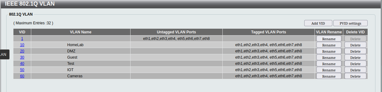
If you click on one of the VLAN number links, you get a screen like this:
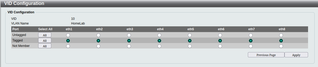
The method with this switch is that you define each VLAN, give it a name and then define how each port interacts with the VLAN.
In this switch, the default VLAN 1 remains the VLAN to which all untagged packets are attached. Then all of the ports are configured as tagged members of all of the custom VLAN’s that I created. Essentially, every port will be able to communicate on every VLAN if the packets are already tagged, and will leave the untagged packets untagged.
I should point out that this is not the final configuration that I intend for this switch. I’m still in the process of sorting out all of my network security and I’m leaving this wide open while I configure everything else and test it. I don’t want something to fail and waste lots of time looking for setup issues in my firewall whilst the actual problem was the wrong VLAN on a port on this switch. This switch is the one closest to my entertainment centre, and has most of the “VLAN unaware” wired devices on my network. Things like my XBox and my IPTV box. Eventually, I’ll be reconfiguring this switch such that those devices go into the IOT VLAN (I think).
Understanding Tagged VLAN Membership
You might find it a little hard to picture how this second case is used at first.
However, if you are using Proxmox for virtualization, you’ll have seen this screen for configuring the networking on a Proxmox host:
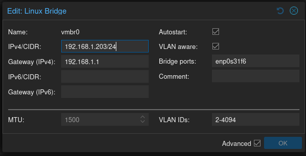
Here the Linux Bridge vmbr0, which defines how the VM’s on the node will connect to the ethernet adapter, is defined. Note the checkbox beside “VLAN aware:”, and the range of “2-4094” that is assigned to “VLAN IDs:”.
Then, when you define the networking for a VM on that Proxmox host, you’ll see this screen:
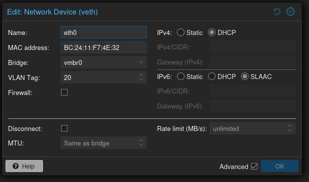
In this screen eth0 is being defined as connecting to vmbr0 and having VLAN tag 20 attached.
What’s important to note is that if we define another Linux container or VM on this same node, attached to the same bridge, but assigned to VLAN tag 30, then it won’t be able to communicate directly with the first VM. Even though they are sharing the exact same hardware.
However, these VM’s will not be able to communicate with anything unless the port on the switch that the host is plugged into is a member of both VLAN’s 20 and 30 as “tagged”.
Firewalls and Routers
The second, and probably most important place you’ll encounter a “VLAN aware” device is a firewall or a router. For sure, both OPNsense and pfSense are very VLAN aware.
Understand that a firewall is always, by definition, a router, and that a router is designed to transfer traffic between ports. Essentially, firewalls use VLAN’s to define multiple network interfaces on the same hardware port. Each VLAN becomes a “device” which can have its own ethernet address.
In OPNsense, you define a VLAN as a device, and attach it to a physical ethernet port and connect it logically to a VLAN defined on the switch. From that point on, you can treat your VLAN device just like any other network port. You can assign it an IP address, you can create firewall rules for it, and you can create a DHCP server for it.
This is what enables you to use VLAN’s to control security inside your network. Once you’ve done this, you’ve created the authoritative connection between a VLAN and a TCP/IP subnet.
Let’s say that you have that VLAN 20 from the screenshot above. On your firewall, you define a network interface called VLAN_DMZ and assign it to your inside ethernet port using VLAN 20. You’re going to use VLAN_DMZ as the gateway for the network 10.10.10.0/24, so you give it the address 10.10.10.1.
Now, if any other device inside your network is on VLAN 20, and if it wants to talk to anything outside VLAN 20 it is going to have to be on 10.10.10.0/24. Otherwise it cannot communicate with the gateway at 10.10.10.1.
You can see from this that the firewall configuration “locks in” VLAN 20 to the 10.10.10.0/24 subnet, and the firewall rules will define how it can behave as a “DMZ”.
So far, none of this particularly uses the isolation qualities of VLAN’s. It really just enables us to have just about as many subnets as we want on our network without having to stuff a new NIC inside our firewall for each subnet.
In fact, you could just ignore the security aspects of the separation qualities of VLAN’s and configure every single port on every single switch that you own to accept traffic from every single VLAN that you create and you probably wouldn’t sacrifice too much actual security. I’m not suggesting that you do this, but it wouldn’t be the end of the world if you did.
DHCP
The one place where it really is useful to have separation between the VLAN’s is the one commonly used TCP/IP service which is truly treated as a broadcast - DHCP.
When a device is attached to the network that has been configured to use DHCP to get its network information it doesn’t initially have an IP address or even any knowledge about the network that it’s plugging into. How does it communicate with the DHCP server on the network without an IP address?
The answer is that it uses pure local broadcast on the IP network. Essentially, all of the communication is performed by using the address 255.255.255.255 which will be seen by every host on the local network. Most importantly, packets addressed to 255.255.255.255 will never pass through a router - they are strictly local.
First, the device broadcasts a “discover” message to the entire network that essentially says, “I’m here! Can anybody give me an address?” Every DHCP server that sees that broadcast will respond by broadcasting an “offer” of an IP address. The new device then picks one of the offers, and “requests” that address be assigned to it (once again by broadcast). The DHCP server that made the offer then broadcasts an “acknowledgement” of the assignment.
This process is known as “DORA”, which means Discover-Offer-Request-Acknowledge.
The key point for us is the part that says, “Every DHCP server that sees that broadcast…”. Now go back and look at the first VLAN picture in this article. See how it says, “Broadcast message in”, and “Broadcast message out”? And see how the VLAN’s prevent the broadcasts from crossing between them?
What this means is that every single VLAN on your network needs its own DHCP server if you want to use DHCP. In our example, we would create a DHCP service for VLAN_DMZ, which listens and broadcasts on VLAN 20.
Once again OPNSense works great here. Using “Dnsmasq DNS and DHCP” - which is the DHCP service that you should be using now - you don’t set up multiple DHCP servers, but you do create up rule sets for different interfaces. OPNSense will then listen on each interface that you’ve configured, and provide an address, mask, gateway and DNS server tailored for that VLAN.
This is the piece that puts it all together.
Once you’ve done this, you can now connect a device to your network configured to use DHCP and assigned to a VLAN - either through the device itself or through the switch that it’s plugged into - and it will be attached to a particular subnet that you have defined for that VLAN.
WiFi
But what about all those devices that connect via WiFi? They’re generally not VLAN aware, and they don’t plug into a switch port that you can configure for untagged packets.
The answer is that most WiFi access points allow you to associate a WiFi SSID with a VLAN. Even consumer grade WiFi routers allow you to set up a “Guest” SSID and associate it with a VLAN.
I’ve been using D-Link DBR-X3000-AP access points, and they have the ability to set up 6 “Guest” zones, each with an SSID and VLAN tag:
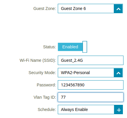
Now, when I’m setting up a new smart plug or other device, I just configure it to connect to my “IOT” SSID, and to use DHCP. Everything else just works. You’ll also have to make sure that whatever switch port you plug the AP into is configured to recognize the VLAN’s that you use for all of the SSID’s that you create.
The Default Setup with ISP Equipment
Chances are that you started out with, and might still have, the WiFi router that your ISP sent you when you signed up. It might, or it might not be a separate component from your Internet modem - you’re better off if it is separate.
Let’s look at what your network looks like with this equipment:
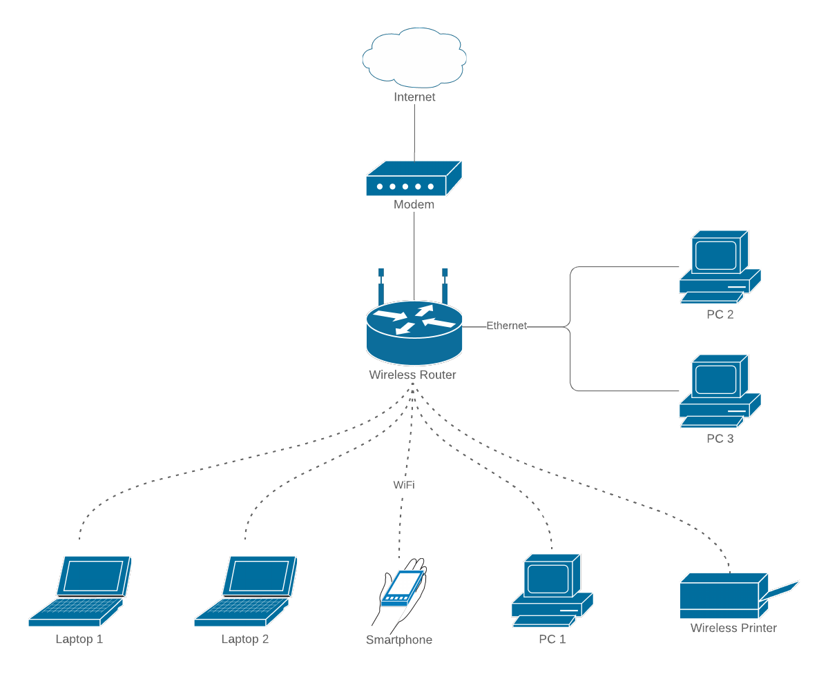
The problem is twofold:
- The WiFi router is integrated with the internet router.
- The consumer grade, plug and play, equipment cannot be configured adequately.
These two items mean that the equipment is great for people who don’t have the technical knowledge to do much more that plug the bits together, and who can’t figure out how to even change the WiFi password. And that’s probably the vast, vast majority of customers that the ISP’s are dealing with.
But if you are building your own, self-hosted, services, you’ll need something different. For instance, with a standard, consumer, WiFi router, you’ll probably have a single “guest” SSID avaliable, and it might even allow you to associate it with a VLAN. But if you really want to use VLAN’s and subnets properly, you’ll need a few more SSID’s. Also, if you are implementing your own firewall, you’ll probably need to turn off all of the routing in your WiFi router, along with things like NAT and DHCP. You’ll probably need to put it into “Bridge” or “AP” mode if that’s possible.
The WiFi router that my latest IP sent me is so simple it doesn’t even have a “Bridge” mode. I didn’t even bother with it so it’s just stayed in the box in a closet.
Generally speaking, you’ll want to replace your WiFi router with a WiFi “Access Point” or “AP”. As soon as you go looking for these, you’ll discover that you’re not in the consumer marketplace any more. Marketting bumpf will talk about how good the devices are for conference rooms or multi-unit dwellings. Access points are fairly cheap, too.
Setting up OPNSense to Use VLAN’s
Let’s take a quick survey of how you would set up OPNSense to enable VLAN’s and subnets on your network with just two physical ethernet ports on your server, one of which is the WAN port - and we won’t talk about that. This isn’t a step-by-step guide, but really just an overview of the things that you need to achieve in order to implement VLAN’s and subnets. If you want step-by-step instructions, you can find tons of them on YouTube.
Creating VLAN Interfaces
When you start out, you’ll have an “Interface” configured for the physical internal ethernet port. This is generally called “LAN”. You’ll neet to create an Interface for each VLAN that you are going to set up.
Creating the VLAN Device
Before you can create an Interface, you’ll need to set up a VLAN device. In the “Interfaces” menu there is a submenu called “Devices” and an item in that called “VLAN”. Click on that option and you’ll get a list of all of the VLAN devices that have already been defined, and then click on the “+” button to add a new one.
You’ll get a screen that looks like this:
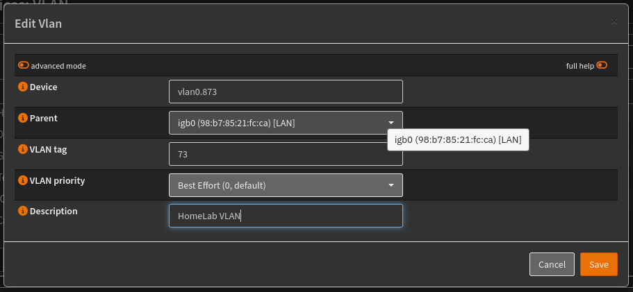
The device name is a bit tricky, it needs to start with “vlan0” and then have some more numeric stuff after that. The parent should be the device associated with your LAN interface. Then you give it whatever VLAN tag that you are going to use in your switches. Give it a description that makes sense to you.
Assigning the VLAN Device to an Interface
The next step seems like something that should probably happen automatically, but doesn’t. In the “Interfaces” menu there is an item called “Assignments”. Click on that and you’ll get a screen with a list of devices that have been assigned to interfaces. Down at the bottom is a little section to add new assignments:
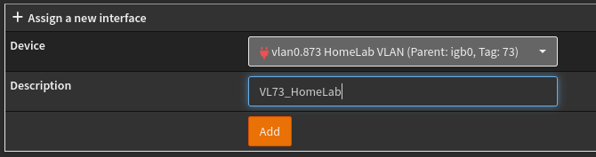
There’s not much to it. Just a dropdown and a textbox for the description. Note that this description is what you are going to see all the time when you deal with just about anything else in OPNSense. So pick a name that makes sense to you.
At this point, you will have created an Interface for your VLAN! But it still needs to be configured.
Connecting Your VLAN to a Subnet
Once you’ve hit “Apply”, you’ll get a new item in the “Interfaces” menu with the name of your Interface. Go ahead and click on it:
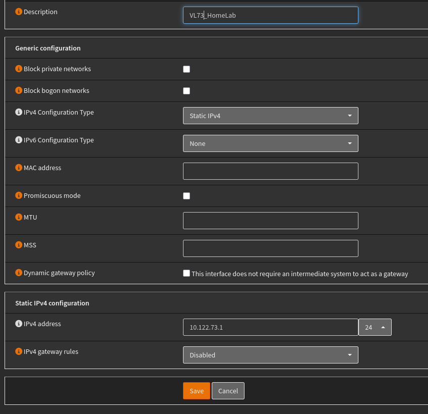
Not shown here is the checkbox to enable the Interface. Be sure to click on that to enable the Interface.
I’m just using IPv4 here, so you I’m not going to do any IPv6. Select “Static” for the IPv4 configuration type and then you’ll see the box at the bottom with address textbox.
That address textbox is where you connect the VLAN to the IP subnet. You are not just giving the Interface an address, you are defining the subnet to which it belongs. That’s what the dropdown box to the right is for. I picked “24” because I want 10.122.73.0 to be the subnet, with a mask of 255.255.255.0.
That’s all you need to specify: enable, static IPv4, address and mask. Hit “Save” and then “Apply”.
Now your Interface and VLAN is set up and ready to go. You’ll see that new Interface name pop up all over the OPNSense UI whenever it’s an option. Most importantly, it will be an option in the Firewall --> Rules menu. Don’t forget that at this point, it has no rules except the default, “Deny Everything” rule, meaning that this subnet is 100% sequestered for outgoing traffic.
Setting Up DHCP
The last step is to configure the OPNSense DHCP service to listen on your new Interface/VLAN.
At the time that I’m writing this, the older DHCP services are being phase out, and KEA is probably overkill for simple home networks. Which means that you should be using Dnsmasq DHCP. So that’s what I’ll show here.
The DHCP configuration is in the “Services” menu. The first thing you’ll need to do is some basic configuration for the service. Click on Services --> Dnsmasq DNS & DHCP to open up the submenu and then click on General. You’ll get a screen that will allow you to enable the service, and then select all of the Interfaces that you want it to work with. Save this and you’re ready to set up your subnets.
Setting Up DHCP Options
Just as when you set up static IP on a device where you need to specify subnet and mask, gateway and DNS servers along with device IP address, DHCP has to provide the same information. The subnet and mask are handled automatically, but you need to configure the rest.
In OPNSense Dmasq the gateway and the DNS servers are treated as “options”. You’ll need to configure these for each Interface. There’s actually a fair number of options available, and you’ll have to pick the correct two.
In the DMasq screen in OPNSense there’s a tab (and a menu item) called “DHCP Options”. This will show a list of the options that you have configured for each Interface. There’s the usual “+” button at the bottom right. Click it and you’ll see a dialogue like this:
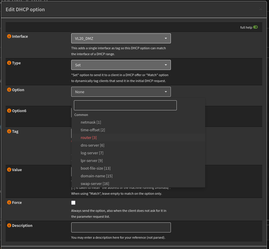
Pick the Interface for your VLAN and select “set” as the action. You need to do this twice. Once for “router [3]” as default gateway address, and once for “dns-server [6]”. It’s probably a good idea to specify a description so that you can see what they are at a glance from the main listing.
That’s It
At this point, you have your firewall configured to support your VLAN’s. It’s beyond the scope of this article to talk about firewall rules, but just remember that each of these subnets is automatically created in a fully sequestered mode. Nothing can get out, and nothing can get in. You’ll have to add the rules to allow devices on these subnets to communicate outside the subnet.
Don’t Forget the Switch
Whatever switch port that LAN on your OPNSense firewall is plugged into needs to be configured to allow traffic tagged with every VLAN that you set up in the firewall to pass through. Otherwise, none of this will work.
Ignoring VLAN’s
The one caveat to all of this is that once a subnet has been connected to a VLAN, nothing outside that VLAN can directly communicate with any address on that subnet that is on the VLAN.
Let’s say that you have three devices on ports 1, 2 and 3 of a managed switch. Ports 1 and 2 are configured to use VLAN 77 for untagged packets while port three is left at the deault configuration, essentially meaning no VLAN processing. The devices are all configured statically to have IP addresses 10.10.10.10, 10.10.10.11 and 10.10.10.12 in order in ports 1, 2 and 3. In this scenario, the devices in ports 1 and 2 can communicate, but the device in port 3 cannot communicate with either one of them, even though it is on the same subnet.
Furthermore, that device on port 3 can only communicate with devices that are on the same subnet and also untagged. This is because the gateway - presumably at 10.10.10.1 - is going to also be on VLAN 77 if everything is configured correctly. This means that the device on port 3 cannot communicate with the default gateway for its subnet, and therefore cannot communicate with any device on another subnet.
At the same time, the devices on ports 1 and 2 can communicate with any device on any other subnet reachable by the firewall, regardless of what VLAN they are on. This is because the traffic leaving the firewall Interface on the other subnet is going to be tagged with the correct VLAN id for that subnet.
You can see that it’s important that once you start using VLAN’s to then use them everywhere, especially if you are configuring devices on subnets that aren’t associated with VLAN1, the default “No VLAN” VLAN.
Conclusion
The first thing to remember is that network security behind your firewall is every bit as important as security between your firewall and the outside world.
It’s incredibly easy to hear about VLAN’s and how important they are to your network security, but it’s much harder to find out how they do that. I’m hoping that this article helps to clear that up. But to recap:
The core of network security is based on controlling TCP/IP traffic. That control is virtually always achieved via a firewall to regulate traffic between IP subnets. VLAN’s work inside your network switches by restricting whether or not data packets will be delivered to particular switch ports and each port on a managed switch is configured such that it will accept packets (incoming or outgoing) with particular VLAN “tags”. Each port can also be configured to assign a specific tag to incoming packets that have no tags on them.
Your firewall is the component that connects VLAN tagging with TCP/IP subnets and TCP/IP traffic control, which, once again is the main way that you implement your security. Each VLAN effectively becomes synonymous with a TCP/IP subnet.
You use this technology to divide your internal network up into subnets that represent different “zones”. Those zones, in turn, hold devices that share a similar trust profile and they are isolated from other zones via your firewall rules.